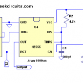
Ok, I’ve been so busy for the past few weeks and I couldn’t make a follow-up from the last article of the 555 timer circuit. So here is another improvised model circuit that will eliminate the unwanted DC offset voltage from the output that affect the previous one discussed. By the way, all previous circuits that I discussed were intended as “low power” class d amp source that is adequate to drive head phones via a coupling capacitor. Continue reading “Full bridge class d amp using 555 timer”
Class D amp made easy with 555 timer IC
This is a continuation of my previous article regarding class d amp using 555 timer chip. Looking back to several schematics on that article, some of you may wonder why I include another 555 as U2 in the drawing. The main purpose of this U2 is to establish constant frequency trigger on pin 2 of U1 in such a way of maintaining stable PWM carrier frequency during audio input modulation. Continue reading “Class D amp made easy with 555 timer IC”
Class D amp using 555 timer
Perhaps 555 timer is the most versatile chip ever introduced during the 70’s and still being used by many due to its inherently innumerable uses such as LED flashers for toys, battery regulators for cars, precision timing device for instrumentations and the list goes on. Not to mention its dirt cheap price and one of the most ubiquitous IC on earth. Continue reading “Class D amp using 555 timer”
Low power class d amp turorial
This article is intended for electronic hobbyist or students alike who are interested in learning the basic operating principle of these audio amplifiers popularly known as class D amp. These types of switching amps are ideally suited for battery operated gadgets and are popularly being used in cell phones, set top boxes, and most MP3 players due to its inherently high efficiency and low power consumption as opposed to linear amps. The sample circuit bellow is for low power headphone amplifier but can also drive small speakers as well.
The basic operating principles of these audio amps are similar to those of switching DC to DC converters utilizing PWM (pulse width modulation). But when used in audio applications, the output is purely in a clock pulses being modulated on its duty cycle in proportion to audio signal as a modulator.
Let’s say at chosen clock frequency of 200 kHz, the quiescent output pulses are at 50% duty cycle without audio but being modulated to +/- 50 when strong audio is present. This will yield an output of from 0 to 100% centered at 50. Continue reading “Low power class d amp turorial”
